
|
|
Ideally suited for rehabilitation of an injured leg, targeted exercise of specific muscle groups, or simply a new experience in range and variety of motion; The Variable Exercise Bicycle (VEB) combines options that are currently available only on stationary devices, with the mobility of a bicycle. Extendible arcuate pedal shafts can be moved independently of each other to allow an injured leg (hip, knee, or ankle) to be held still at first and to have motion and force introduced gradually as the healing-process allows. The pivot points of the pedal shafts can be repositioned relative to the frame and the seat and handlebars can be moved forward and rearward to vary the exercise regime. The VEB has an infinite array of possible gear ratios for the efficient transfer of energy to the rear wheel regardless of the direction or degree of pedal travel. In this configuration the right pedal shaft is extended to serve as a kickstand, the oval-shaped plates onto which the pedal shafts pivot are in the second positioning notch (slightly clockwise), the seat and handlebars are mid-range, and the gear ratio is low as evidenced by the minimal radial distance of the pulley-carrying bracket on the pedal shaft and the one near the top of the oval-shaped plate, from the pivot point of the pedal shaft. | |
 |
In this view the pedal plates are rotated to their extreme clockwise position (fourth notch on the top of the pedal plates), the pedal shafts are fully extended, and the seat and handlebars are rearward. the small separation of the axis of hip rotation of the rider from that of the pedal shafts results in most of the leg movement being in the hips and focused on the gluteus maximus and the lower abdominal muscles. The pedals can be moved alternately (as shown) in order to simulate no-impact running exercises. They can also be moved together in the same direction resulting in torque being transmitted to the upper body. This torque can be resisted by triceps, biceps, deltoids, pectorals, abdominal muscles, erectors ect. To effect a complete upper body workout. |
| The pedal shafts have been shortened, the pedal plates are in the extreme counter-clockwise position (first notch), and the seat and handlebars are forward. With this geometry there is a large separation between the axis of the hips of the rider and that of the pedal shafts so there is greater involvement of the quadriceps and biceps femoris muscles that extend and flex the knees. Also the upper abdominal muscles are more involved as the pedal lift is higher. | 
|
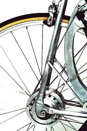 |
This is a close-up of the two pulleys on the right side of the rear hub. They are equipped with internal roller clutches which transmit torque to the rear wheel only in the forward direction and free-wheel when turned rearward. The inner pulley engages the rear hub on the pedal downstroke only and it has two slots. The diameter of the inner slot is approximately twice as large as that of the outer one. In this case the downstroke cable is positioned in the large-diameter inner slot which effects a low-gear range that makes it possible to climb very steep hills. Once a hill is crested and the gear ratio increased, subsequent pedal downstrokes automatically return the cable to the smaller, high gear slot. There is no chance of the cables slipping on the pulleys as they are positively locked by knotted ends. |
| This close-up shows the pedals in synchronous up position with the pedal plates in the third notch and the gear ratio at its highest value as evidenced by the extreme radial distance of the two pulley brackets from the pedal shaft pivot point. The pedal shafts are in the fifth extended position. | 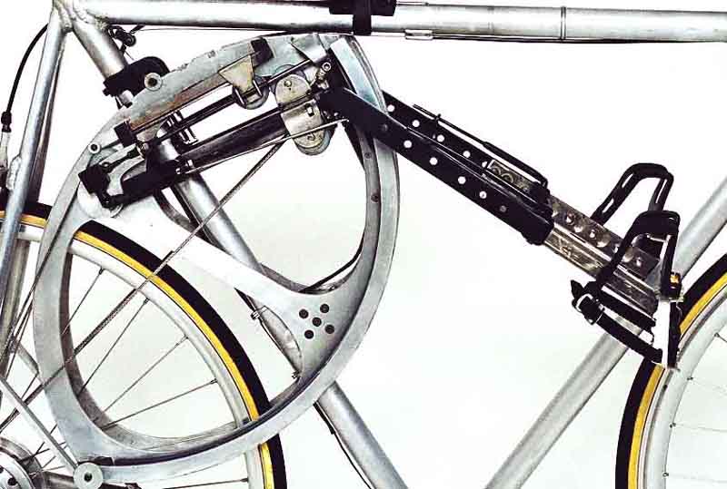
|
 |
This is a comprehensive close look at the routing of the
one-eight-inch 2,000 pound test spectra cable that transmits power from the
pedals to the rear wheel silently and efficiently as it runs in ball-bearinged
nylon pulleys. The pedal plates are in the first notch and the gear ratio is
mid-range. In this case the upstroke cable extends past the pulley on the
pedal shaft and clips onto a pin at the bottom of the pedal plate. This
equalizes the gear ratio and consequently the force involved in up and down
pedal movement and makes possible a unique balance when the pedals are moved
alternately as the up force on one side equals the down force on the other.
Moving both pedals together produces abdominal crunches and generates torque
on the rider that can be utilized in various ways to exercise upper-body
muscles. The round black object mounted onto the outer rear hub pulley is
the smaller diameter tensioning pulley. All four rear hub pulleys have these
smaller ones mounted on them. They act to assure that there is never any
slack in the main power cables. They accept .060 inch spectra cables with 5
pounds of tension supplied by constant-force stainless steel springs that
unroll from the spools located just behind the central mounting hole of the
frame.
|
| Here is an oblique frontal close-up of the pedal plate assembly showing the small reversible electric motor (lower black object between plates) and the worm drive assembly (upper object) which turns the threaded rods on the pedal shafts and at the top of the plates in order to change the effective gear ratio on both sides simultaneously in a smooth, continuous manner. | 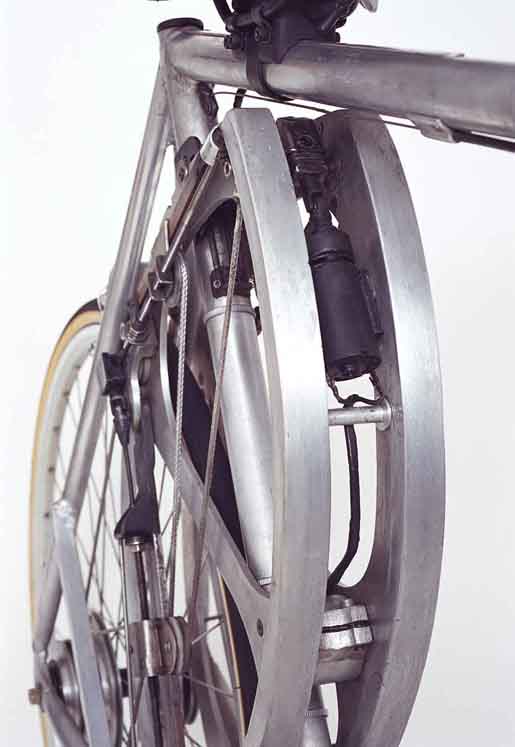
|
|
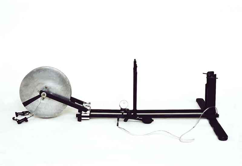
The stationary base is unfolded and ready to accept the VEB for use indoors. It takes less than a minute to secure the VEB in this base and about 16 seconds to remove it. |
| The VEB is secured in the stationary base. The aluminum discs house a pneumatic brake and a central hub that is held in pressure contact with the rear tire by over-the-center locks that act on the rear frame struts. A through-bolt securely holds the VEB in the base, a velcro strap keeps the front wheel oriented, and a sphygmomanometer clamps onto the handlebars to control the resistance of the pneumatic brake between the two discs. The plastic tubing that communicates the air pressure to the brake is seen hanging from the handlebars. |

|

|
This is an
oblique rear view of the VEB in the stationary base which has no
resistance as demonstrated by the gauge on the handlebars.
|
| This is a close view of the based VEB with resistance (note the needle on the pressure gauge). The gear-controlling DPDT switch is on the right handlebar, the clamp that holds the pedal plate release lever is just left of the speedometer (black square), and the allen wrench for moving the handlebars is held by an elastic band between the speedometer and the pressure gauge. |  |
